The PIDFF function block in Schneider Electric EcoStruxure Control Expert (formerly Unity Pro) is the most feature-complete PID controller within the CONT_CTL library, available across:
- Modicon Quantum
- Premium
- M340
- M580
The “FF” stands for Feedforward, enabling the controller to:
→ compensate for measurable disturbances before they impact the process
Unlike simpler blocks (PID, PI_B, PID1), PIDFF supports:
- Feedforward compensation
- Cascade control
- Bumpless transfer
- Advanced mode management
It is widely used in complex industrial process control applications.
PIDFF Architecture & Control Strategy
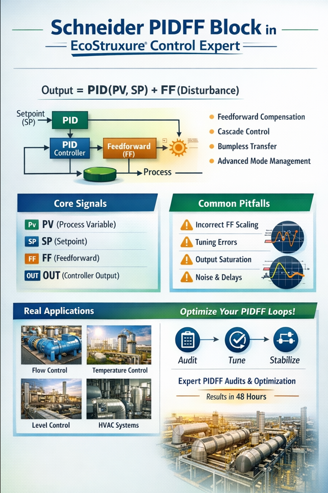
Control Output
Output = PID(PV, SP) + FF(Disturbance)
Key Signals
- PV → Process Variable
- SP → Setpoint
- FF → Measured disturbance input
- OUT → Controller output
- OUTD → Output tracking / display
- MAN_AUTO → Manual / Auto selection
- TR_S / TRI / TRS → Tracking & cascade inputs
- RCPY → Integral preloading (startup conditioning)
- PARA → Full configuration structure (Para_PIDFF)
- INFO / STATUS → Diagnostics and error handling
When Should You Use PIDFF?
Use PIDFF When:
- Disturbance is measurable and reliable
- Fast compensation is required
- Process interaction exists (e.g. cascade control)
- High performance and stability are critical
Avoid PIDFF When:
- Disturbance is not measurable
- Signal is noisy or delayed
- Process is simple and stable
- Dead time dominates the system
In such cases, a well-tuned standard PID is often more robust.
Feedforward Engineering — What Actually Matters
How It Works
- Disturbance signal is scaled
- Converted into output contribution
- Added directly to controller output
Key Parameters (Para_PIDFF)
- ff_inf / ff_sup → disturbance input scaling range
- otff_inf / otff_sup → output contribution mapping
Critical Field Gotcha
If:
ff_inf = ff_sup
Feedforward is completely disabled.
Engineering Reality
Feedforward must be:
- Gain-matched to process
- Time-aligned with process dynamics
- Noise-filtered
Otherwise it causes:
- Overcompensation
- Oscillations
- Output saturation
Why PIDFF Loops Fail in Real Plants
Common Failure Modes
- Incorrect feedforward scaling
- PID tuned without feedforward active
- Output saturation (PID + FF exceeds limits)
- Anti-windup not configured properly
- Incorrect control direction (direct vs reverse)
- Noisy or delayed feedforward signal
Result:
- Oscillations
- Slow response
- Unstable operation
The Para_PIDFF Structure (Critical Configuration)
The Para_PIDFF DDT defines all behaviour of the controller.
Scaling Parameters
- pv_inf / pv_sup → PV range (must not be equal)
- out_inf / out_sup → hardware limits
- out_min / out_max → operational limits
- ff_inf / ff_sup → FF input scaling
- otff_inf / otff_sup → FF output mapping
Tuning Parameters
- Kp → proportional gain
- Ti → integral time (TIME format required)
- Td → derivative time
- Kd ≥ 1 → derivative filter
- dband → deadband
- outrate → output rate limiting
Critical Pitfall (Very Common)
Ti = 10
This is interpreted as 10 ms, not 10 seconds.
Correct usage:
Ti = T#10s
This mistake alone causes severe instability in real systems.
Operating Modes & Bumpless Transfer
PIDFF supports:
- Manual mode → operator controls output
- Auto mode → closed-loop operation
- Tracking mode → cascade synchronization
Key Capability
Bumpless transfer:
- No output jump when switching modes
- Integral term is automatically aligned
Cascade Control with PIDFF
Architecture
- Primary loop → sets SP of secondary
- Secondary loop → drives actuator
Critical Requirements
- Secondary loop must be 3–5× faster
- Primary must track secondary during transitions
- OUTD + TRI provide back-calculation
Poor configuration results in large output disturbances (“bumps”).
AUTOTUNE — Reality vs Expectation
PIDFF integrates with the AUTOTUNE block, but:
Practical Reality
- Provides initial estimates only
- Struggles with:
- large dead time
- nonlinear systems
- actuator saturation
Always refine tuning manually after autotune.
Known Field Issues & Practical Workarounds
Observed in Real Systems
- Mode-switch anomalies (rare firmware behaviour)
- Parameter reset after download
- AUTOTUNE wiring confusion
- Documentation gaps
Practical Workarounds
- Explicitly initialise PARA structure
- Use RCPY for startup stabilisation
- Validate scaling after download
- Avoid overly aggressive enable toggling
These are real-world issues rarely covered in manuals.
PIDFF Implementation Checklist
Before commissioning:
- Feedforward signal measurable and stable
- Feedforward scaling configured correctly
- PID tuned with feedforward active
- Output limits properly defined
- Anti-windup mechanisms verified
- Time alignment validated
- Cascade loops tuned correctly
Real Industrial Applications
PIDFF is widely used in:
- Flow control with pressure compensation
- Temperature control with load disturbances
- Level control with inflow variation
- Energy and HVAC systems
It is most effective where disturbances are measurable.
Business Impact
Poor PIDFF implementation leads to:
- Production losses
- Energy inefficiency
- Equipment wear
- Unstable operations
- Increased operator intervention
The cost of poor tuning is often hidden but significant.